
This circuit is a dummy car alarm LED flasher designed to deter potential thieves by making it look like an active security system is installed. Why bother with all this circuitry when high-brightness flashing LEDs/lights exist for this purpose? Because it's fun! And, depending on the design, most are just a simple LED that flashes the whole time while power is applied with no way to stop it while driving - except by adding a series switch. This leads to another problem of remembering to turn it on while the vehicle is parked and unattended.
Circuit Description
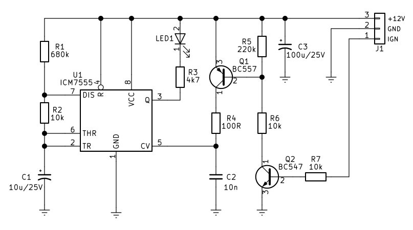
It is powered by a 12V vehicle battery connected through terminal J1, where bulk capacitor C3 filters the supply rails.
The core of the circuit is centered around U1, an ICM7555 low-power CMOS timer configured as an astable multivibrator. Resistor R1, resistor R2, and capacitor C1 determine the primary charge and discharge timing cycle, causing the output at pin 3 to pulse periodically. When the output goes high, current flows through current-limiting resistor R3 to illuminate LED1, creating a flashing warning light effect.
The circuit features an ignition-sensing disable function governed by transistors Q1 and Q2. When the vehicle's ignition is turned on, 12V is applied to the IGN pin of terminal J1, sending a signal through resistor R7 to the base of Q2 (a BC547 NPN transistor). This causes Q2 to turn on, which pulls the base of Q1 (a BC557 PNP transistor) low via voltage divider resistors R5 and R6. When Q1 turns on, it routes current through resistor R4 to charge or bias capacitor C2 connected to the control voltage pin (pin 5) of the timer. This action effectively disables or inhibits the 555 oscillator while the vehicle is running, ensuring the dummy alarm only flashes when the ignition is off and the car is parked.
Why it stops oscillating
- Overrides internal dividers: Pin 5 is connected directly to the internal 3-resistor voltage divider
- Raises threshold voltage: Forcing Pin 5 to VCC changes the upper comparator reference level from 2/3 of VCC to the full VCC
- Prevents C1 capacitor trip: The external timing capacitor C1 can never charge above VCC to trigger the upper comparator
- Locks the output: The internal flip-flop gets stuck in one state, halting the cycle
What happens to the output
- Stays HIGH: In standard astable configurations, the output (Pin 3) will typically lock into a continuous HIGH state
- Discharge pin opens: The discharge transistor (Pin 7) turns off, allowing the capacitor to charge up toward VCC and stay there
and, as LED1 only ever has current flowing through it when the output state of the 7555 is low, it stays extinguished while the ignition is on. This operation is designed to prevent being distracted by the LED flashing every few seconds while driving. The LED should be a 5mm high-intensity (4000 - 10000mcd, or so) red device.