
This circuit is a temperature-controlled DC fan speed controller (often used for cooling computer components, amplifiers, or enclosures). It uses a thermistor to monitor temperature and varies the speed of a 12V fan using Pulse Width Modulation (PWM) generated by a 555 timer. It was mainly intended to be used with high-powered Class-AB or Class-D amplifiers, where adequate forced cooling is mandatory.
Circuit Description
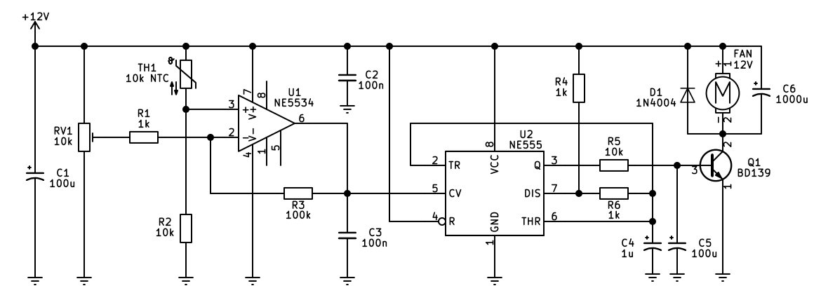
The operation begins at the temperature sensing and amplification stage built around op-amp U1 (an NE5534). Component TH1 is a 10k negative temperature coefficient (NTC) thermistor, meaning its resistance decreases as the temperature rises. Potentiometer RV1 acts as a manual threshold adjuster, forming a voltage divider alongside R1 and R2. U1 functions as a linear error amplifier featuring a 100k negative feedback resistor (R3) connected between its output (pin 6) and its inverting input (pin 2). This feedback configuration provides the op-amp with a defined analog gain rather than operating it as a simple digital on/off comparator.
As the temperature increases, the resistance of TH1 drops, altering the voltage at the non-inverting input (pin 3) of U1. The amplifier scales this difference relative to the reference voltage set by RV1, producing a smooth, proportional control voltage at its output.
This output is fed directly into the control voltage pin (pin 5) of the NE555 timer oscillator (U2). The hotter TH1 gets, the more U1 varies this control voltage, which dynamically shifts the internal threshold levels of the 555 timer. This modulation changes the charging and discharging rates of the timing capacitor connected to pins 6 and 7, altering the duty-cycle of the square wave output at pin 3. Consequently, as temperature increases, the output duty cycle changes to increase the speed of the fan, until at a certain point the control voltage drives the circuit such that the fan is running at full speed.
The modulated PWM signal from the 555 timer is then passed to the fan driver stage through resistor R5 to the base of transistor Q1 (a BD139 NPN power transistor). Instead of supplying a lower constant DC voltage (which risks stalling the motor) transistor Q1 acts as a high-speed electronic switch that rapidly pulses the fan fully on and off according to the timer's duty cycle. This sends bursts of current to the motor.
Finally, protection and filtering components ensure stable operation. Flyback diode D1 is wired in parallel with the fan motor to clamp high-voltage inductive kickbacks when Q1 switches off, protecting the transistor from damage. Bulk capacitors C1 and C6 stabilize the supply rails and filter out electrical noise generated by the switching motor load. C6's role is important, as it filters out the PWM switching noise that can be heard as a slight "squeal" from the fan motor as it's rotating at slower speeds.
One thing to note, TH1 needs to be in close contact with the heatsink to be monitored, such as the amplifier's main heatsink.
PCB
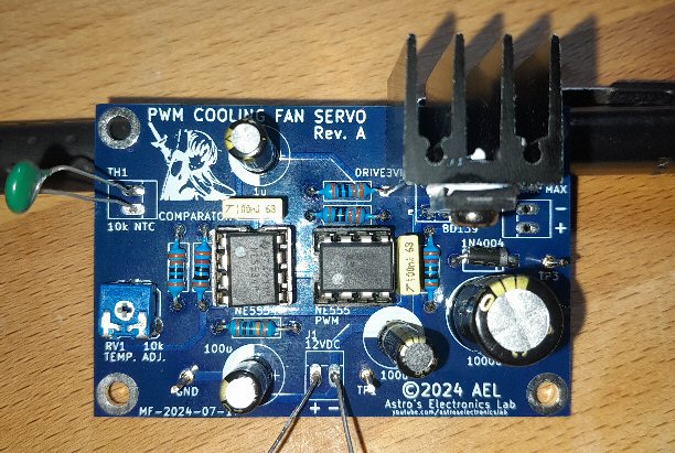
As PCB is available from PCBway as a shared project. I don't use PCBway much anymore since they removed the Paypal payment option for all purchases - which is kind of annoying, as they've basically limited their customer base. Most every other website uses Paypal, however PCBway have made it pretty much credit card (as well as other non-useful payment methods such as Payoneer, which doesn't work outside the US) making it very inconvenient. I have since moved over the JLCPCB, but they don't offer "shared projects" like PCBway do.