
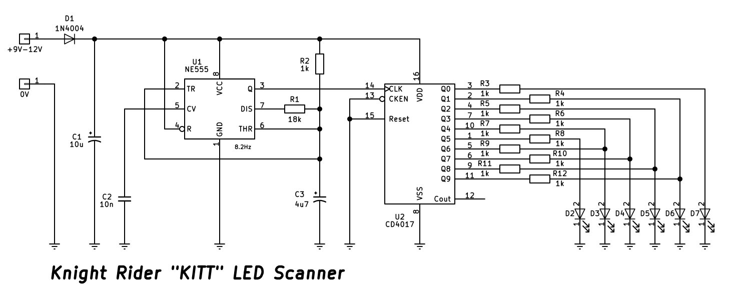
This circuit is a classic electronic novelty project inspired by the iconic sweeping red light "scanner" on the front of "K.I.T.T.", the modified 1982 Pontiac Firebird Trans Am from the 1980s TV show Knight Rider. It creates a back-and-forth scanning light effect using an NE555 timer and a decade counter.
Circuit Description
The circuit operates by connecting a 9V to 12V DC power source through diode D1, which provides reverse-polarity protection, while bulk capacitor C1 smooths and filters the input supply.
The heart of the timing signal is U1, an NE555 timer integrated circuit configured as an astable multivibrator oscillating at approximately 8.2Hz. Resistor R1, resistor R2, and capacitor C3 govern this oscillation frequency by setting the charge and discharge rates for the timing network. The output pulses from pin 3 of the NE555 timer are fed directly into the clock input (pin 14) of the second IC.
The counter stage utilizes U2, a CD4017 decade counter/divider chip. As each clock pulse arrives from the 555 timer, the CD4017 sequentially steps its active output high from Q0 through Q9, and then cycles back.
The output pins of the decade counter are connected through current-limiting resistors R3 through R12 to a row of LEDs labeled D2 through D7. In a true bidirectional Knight Rider scanner, diodes or complex steering logic are typically used to route the counting sequence back and forth across the LEDs to create the bouncing sweep effect. As the counter steps through its sequence, it lights the LEDs in a sweeping motion, mimicking the famous front-end scanner of K.I.T.T.