
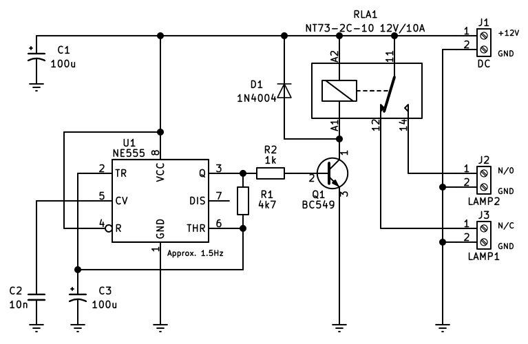
This circuit is a 12V relay-based flasher designed to automatically cycle power between two output channels or lamps at a frequency of approximately 1.5Hz. It uses an NE555 timer integrated circuit to generate a square wave that switches a relay on and off.
Circuit Description
The operation begins with the power input at terminal J1, where a 12V DC source supplies the circuit. Capacitor C1 acts as a bulk filtering capacitor to smooth out power supply fluctuations and stabilize the 12V rail.
The core timing signal is generated by U1, an NE555 timer configured as an astable multivibrator. Resistor R1 and capacitor C3 dictate the charging and discharging timing cycle, resulting in an oscillation frequency of roughly 1.5Hz. Capacitor C2 is tied to the control voltage pin to filter out noise, while the reset pin is tied high to ensure continuous operation.
The square-wave output from pin 3 of the NE555 timer drives the switching stage through current-limiting resistor R2, which connects to the base of transistor Q1, a BC549 NPN transistor. When the timer output goes high, transistor Q1 turns on and draws current through the coil of relay RLA1 (an NT73-2C-10 12V/10A relay). When the timer output goes low, transistor Q1 turns off, de-energizing the relay coil. Diode D1 is placed in reverse-bias across the relay coil to serve as a flyback diode, clamping harmful voltage spikes generated when the relay coil switches off.
When relay RLA1 energizes and de-energizes, its internal common contact toggles between the normally open and normally closed positions. This mechanical switching alternates power between output terminal J2 (connected to Lamp 2) and output terminal J3 (connected to Lamp 1), creating a flashing or alternating indicator effect.