
WARNING: THIS CIRCUIT INVOLVES CONNECTING DIRECTLY TO THE AC MAINS. IF YOU ARE NOT COMFORTABLE AROUND MAINS VOLTAGES, OR KNOW WHAT YOU'RE DOING, DO NOT ATTEMPT THIS CIRCUIT.
This circuit is a mains-powered electronic switch or relay controller that allows a low-voltage control signal, push-button, or trigger to safely switch high-voltage AC mains power to a transformer or load. This circuit can be used in an amplifier if you want to use a momentary push-button switch to turn it on and off. Further adaptation could be made to provide a pulse from an MCU to control the switching so the circuit could be turned on or off via a remote control. I'll leave these further modifications up to the reader.
Again, I must stress that the relay contacts are connected directly to the mains - which could be potentially lethal if you're unsure of what you're doing. For testing purposes, I suggest the "transformer" being switched should be a DC load with an external DC power supply connected to "LIVE" and "NEUTRAL" pins. The 9V AC input for the logic circuitry can come from a simple AC wall-wart (power adapator), or connect the roughly 12V DC directly to the circuit after DB1.
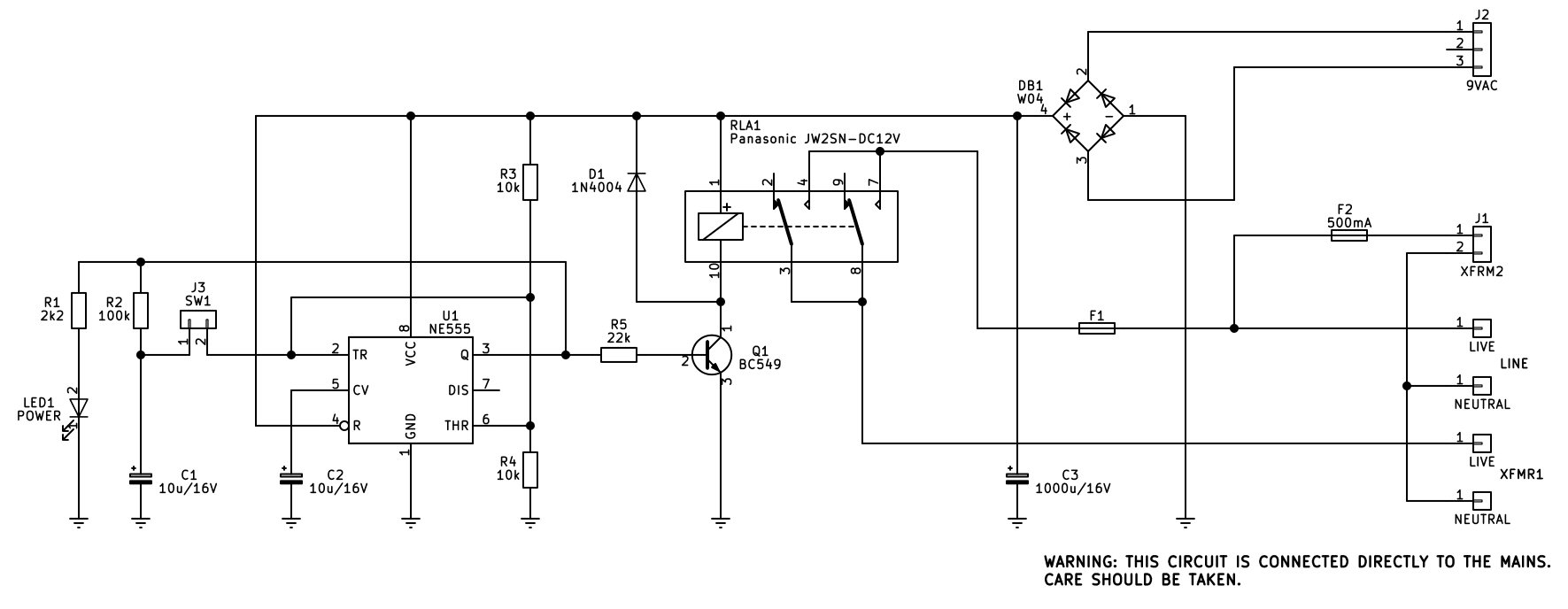
Circuit Description
The circuit receives AC mains power through the terminal blocks labeled Live and Neutral. A portion of this AC voltage is stepped down by a smaller transformer via J1, with the lower 9V AC secondary connected to J2 which is then rectified through a bridge rectifier (DB1) and smoothing capacitor (C3) to provide a low-voltage DC supply rail for the timing and control logic. An LED indicator (LED1) paired with resistor R1 provides a visual power-on confirmation.
The core control logic is built around an NE555 timer integrated circuit (U1) configured in a bistable or toggle/latch arrangement. When power is first applied, capacitor C2 holds the trigger pin (pin 2) low momentarily, ensuring that U1 starts in a low or "off" state. Switch J3 acts as a manual trigger input. Pressing or toggling J3 pulls the trigger pin low, changing the state of the timer's output at pin 3.
When U1 is high or "on", the relay is energized; pressing the switch again toggles the timer output back to a low state, de-energizing the relay and cutting off power to the load. Furthermore, if the switch is pressed and held, the AC coupling through capacitor C1 prevents continuous toggling by blocking a sustained DC level, meaning the circuit will trigger once and remain in that state until the switch is released and pressed again.
The output of the NE555 timer drives the switching stage via current-limiting resistor R5, which connects to the base of transistor Q1 (a BC549 NPN transistor). When the timer output goes high, transistor Q1 turns on, drawing current through the coil of relay RLA1 (a Panasonic JW2SN-DC12V). Diode D1 is placed in reverse-bias across the relay coil to act as a flyback diode, clamping harmful voltage spikes when the relay coil is de-energized.
When relay RLA1 activates, its internal contacts physically switch the AC mains lines connected to the input and output terminals (such as XFMR1 or XFMR2), routing high-voltage power to the intended destination load or transformer (XFRM1). Fuses F1 and F2 provide crucial overcurrent protection for the mains-connected side of the circuit, ensuring safety against short circuits or overloads. The value of F1 is chosen to match the particular transformer primary that is being switched.