
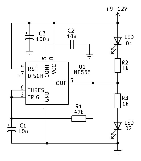
This circuit functions as an astable multivibrator built around the popular NE555 timer integrated circuit, specifically configured to create an alternating flashing effect often used for model railway crossing signals.
Circuit Descrition
Resistor R1 (the 47k resistor) which loops back directly from Pin 3 (the Output) to the junction of the timing capacitor C1, Pin 2 (Trigger), and Pin 6 (Threshold). Pin 7 (Discharge) is left completely unconnected. This specific configuration makes it a simpler, single-resistor relaxation oscillator rather than a standard dual-resistor astable circuit.
When power is applied to the circuit, capacitor C1 begins to charge and discharge continuously. The 555 timer monitors the voltage across this capacitor, and whenever the voltage falls below one-third of the supply voltage or rises above two-thirds of the supply voltage, the internal flip-flop inside the chip switches state. This continuous charging and discharging forces the output pin, Pin 3, to constantly alternate between a high voltage state and a low voltage state.
The clever part of this schematic lies in how the output pin drives the two LEDs, D1 and D2. Instead of a traditional flasher circuit where an LED is simply connected between the output and ground, this circuit places the output pin right in the middle of a voltage divider branch that stretches from the positive supply rail down to ground.
When Pin 3 switches to a high state, it creates a potential barrier for the top LED branch, meaning current instead flows outward from Pin 3, through resistor R3 and down through LED D2 to ground, causing D2 to illuminate. Conversely, when Pin 3 drops to a low state near zero volts, it acts as a current sink. Current then flows from the positive supply rail down through LED D1 and resistor R2, straight into Pin 3, which causes D1 to illuminate while D2 turns off.
As the 555 timer oscillates back and forth, Pin 3 continuously alternates between sourcing and sinking current. This causes the two LEDs to trade places rapidly, creating a back-and-forth flashing warning light. Meanwhile, components like C2 and C3 act as decoupling and filtering capacitors to smooth out electrical noise and stabilize the power supply, ensuring the oscillator runs smoothly and reliably.
Construction
Construction of this should be relatively straight-forward on a piece of veroboard or strip-board, as it only uses a handful of components. Just watch polarities of components. The two LEDs (D1 and D2) can be any 3mm or 5mm red LED of around 600mcd (milli-candelas); the forward voltage of them (Vf) can be 1.8V to 2.2V.
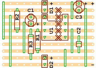
I would suggest not running the circuit any higher than 12V DC, nor lower than 9V DC. If it was run lower than 9V DC, say 5V DC, the flash rate would appear a lot slower and the LEDs would be marginally dimmer. If you wanted to run this on 5V DC, modification to component values would be necessary. R1 would probably need to be lowered to 22k (or there abouts), and R2 and R3 would be lowered closer to 470 ohms.
Conclusion
In conclusion, this elegant 555 timer circuit cleverly utilizes a single-resistor feedback loop and a push-pull output configuration to generate an automated, rhythmic switching action. While it is famously nicknamed a railway crossing flasher due to its uncanny ability to mimic alternating warning lights on model train layouts, its underlying utility extends far beyond that niche. By simply adjusting the values of resistor R1 and capacitor C1 to change the oscillation frequency, this versatile design can be adapted for a wide variety of electronic projects, including alternating hazard indicators on construction toys, custom bicycle safety blinkers, or eye-catching indicators for hobbyist electronics and maker projects.