
This circuit is a simple 555 timer-based flasher, designed to periodically switch a 12V lamp on and off. The NE555 generates a low-frequency oscillation of approximately 1.2 Hz, which drives the IRF540N MOSFET and allows it to switch the relatively high-current required by the lamp. In its day, a circuit such as this could have been used for a warning beacon, hazard indicator, emergency light or other visual alarm, where a regularly flashing lamp was required.
However, traditional incandescent and halogen globes are now largely on the way out, having been superseded by considerably more efficient and longer-lived LED technology. An LED-based version of this circuit would be smaller, more efficient and place much less demand on the switching transistor. Nevertheless, this circuit is included largely for posterity - it demonstrates a classic and very common application of the 555 timer and shows how a simple oscillator can be used to control a higher-current load.
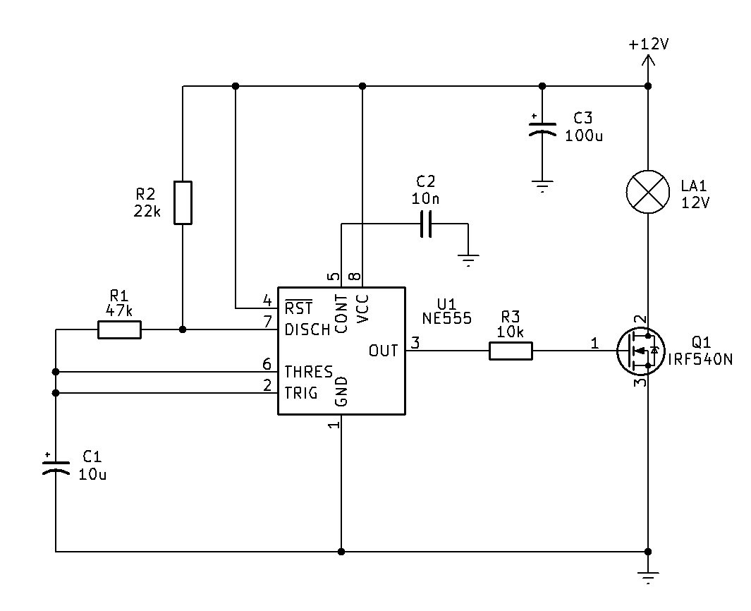
Circuit Description
The NE555 is wired in its standard astable mode. Pins 2 (TRIG) and 6 (THRES) are connected together and monitor the voltage on C1. Pin 4 (RESET) is tied to +12 V so the timer is permanently enabled, while C2 on pin 5 provides control-voltage bypassing. C3 is simply supply decoupling for the 555.
When the circuit starts, C1 is discharged. The 555 output at pin 3 goes high and its internal discharge transistor at pin 7 is switched off. C1 can therefore charge from the +12 V supply through:
+12V → R2 (22k) → R1 (47k) → C1
The voltage on C1 rises exponentially until it reaches approximately 2/3 of the supply voltage. At that point the threshold comparator inside the 555 changes state.
The 555 then switches its output low and turns on its internal discharge transistor at pin 7. C1 now discharges through R1 (47k) and the discharge transistor:
C1 → R1 → pin 7 → ground
When C1 falls to approximately 1/3 of the supply voltage, the trigger comparator changes state again. The 555 output goes high, pin 7 switches off, and C1 begins charging again. With these current component values, the frequency at which the 555 timer oscillates at is approx. 1.2Hz. The lamp consequently flashes about once per second. This process continuously repeats, producing a rectangular waveform at pin 3.
Pin 3 drives the gate of Q1, the IRF540N, through R3 (10k). Q1 is being used as a low-side switch. The lamp is connected between +12V and the MOSFET's drain, with the source connected to ground.
When pin 3 goes high, Q1 turns on and current flows:
+12V → LA1 → Q1 → ground
so the lamp illuminates.
When pin 3 goes low, Q1 turns off and the current through the lamp stops, extinguishing it. Thus the 555 doesn't actually carry the lamp current itself. It generates the timing signal, while Q1 handles the lamp current.
One small point worth noting is that the IRF540N isn't a particularly good logic-level MOSFET. With a 12V supply the 555 can provide a sufficiently high gate voltage for it to turn on reasonably well, but if LA1 draws substantial current, a genuine logic-level MOSFET would generally be a better choice.
Note: if driving a lamp of greater than 5W, heatsinking of Q1 would be required.
Conclusion
So, in summary, R2/R1/C1 establish an approximately 1.2Hz astable oscillator, the 555 produces the switching waveform, and Q1 translates that low-current waveform into the relatively high-current required by the 12V lamp.