
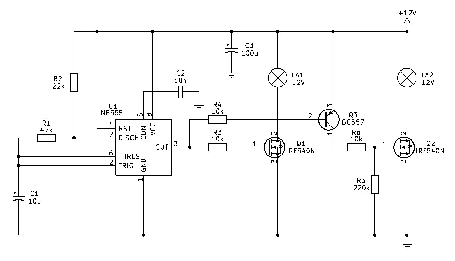
This circuit is an alternating dual-lamp flasher powered by a standard 12V supply. At its heart is an NE555 timer IC (U1) configured as an astable multivibrator, oscillating at approximately 1.2Hz.
The output of the timer (Pin 3) toggles rhythmically between high and low states. This square-wave signal is split to drive two separate high-current power MOSFETs (Q1 and Q2, IRF540N) via a transistor inverter stage (Q3, BC557). As a result, when lamp LA1 turns on, lamp LA2 turns off, and vice versa—creating a continuous, alternating flashing effect.
Because of its robust design and alternating output, this circuit can be adapted for several visual warning and signaling systems:
- Model Railway Crossing Lights: Perfectly mimics the alternating red flashers (wig-wags) found at level crossings
- School Bus "40 When Lights Flash" Signage: Aligns with safety warning systems used on Australian school buses to alert motorists to reduce speed when children are boarding or disembarking
- Emergency & Warning Beacons: Serves as a low-cost alternating hazard light for stationary vehicles, construction zones, or security alarms
- Decorative & Display Lighting: Useful for attention-grabbing displays, alternating indicators, or costume electronics requiring synchronized flashing
Note: it would be inadvisable to put this circuit of a vehicle; as flashing lights on a vehicle for "no reason" is not only distracting to other drivers, but could be potentially illegal.
However, traditional incandescent and halogen globes are now largely on the way out, having been superseded by considerably more efficient and longer-lived LED technology. An LED-based version of this circuit would be smaller, more efficient and place much less demand on the switching transistors. Nevertheless, this circuit is included largely for posterity - it demonstrates a classic and very common application of the 555 timer and shows how a simple oscillator can be used to control higher-current loads.
Circuit Description
Unlike the previous circuit, which simply switched one lamp on and off, this arrangement uses the 555 oscillator to drive two MOSFET switching stages in opposite states, so that LA1 and LA2 alternate.
The left-hand section is the familiar NE555 astable oscillator. R2, R1 and C1 determine the oscillation frequency. With R2 = 22k, R1 = 47k and C1 = 10u, the theoretical frequency is approximately 1.2Hz. The square-wave output from pin 3 is then used to control the two lamp switching circuits.
When pin 3 goes high, the gate of Q1, the IRF540N, is driven through R3 (10k). Q1 turns on and provides a path to ground for LA1:
+12V → LA1 → Q1 → ground
LA1 therefore illuminates.
At the same time, the high output from the 555 is applied through R4 (10k) to the base of Q3, which is a PNP transistor. Since Q3's emitter is connected to +12V, bringing its base high means there is very little base-emitter voltage across it, so Q3 switches off.
With Q3 off, there is no path to raise the gate of Q2 - another IRF540N MOSFET. R5 (220k) pulls the Q2 gate down to ground, keeping Q2 switched off. Consequently, LA2 remains extinguished.
So during this half of the cycle:
LA1 ON — LA2 OFF
When the 555 output switches low, Q1's gate is pulled low through the 555 output, so Q1 turns off and LA1 goes dark. The low voltage is also applied to the base of Q3 through R4. Because Q3 is a PNP transistor with its emitter connected to +12V, its base being pulled low causes it to turn on. Q3 now provides a path from +12V through its collector and R6 (10k) to the gate of Q2. The gate of Q2 therefore rises towards +12V and Q2 turns on.
Current can now flow:
+12V → LA2 → Q2 → ground
so LA2 illuminates.
R5 provides a gate-to-ground pull-down for Q2, ensuring that Q2 is firmly turned off whenever Q3 isn't supplying its gate with positive voltage. R6 limits the instantaneous gate current and isolates Q3 from the capacitive MOSFET gate.
During this half of the cycle:
LA1 OFF — LA2 ON
The result is therefore:
555 HIGH → Q1 ON → LA1 ON → Q3 OFF → Q2 OFF → LA2 OFF
then:
555 LOW → Q1 OFF → LA1 OFF → Q3 ON → Q2 ON → LA2 ON
The two lamps consequently alternate back and forth, producing the familiar alternating warning-beacon effect, which each lamp in turn being on for about 400ms.
Note: when powering globes above 5W, it will be necessary to heatsink both Q1 and Q2.
Conclusion
In summary, this circuit uses a 555 timer to generate a low-frequency square wave of approximately 1.2 Hz, with the two MOSFET switching stages arranged so that the lamps alternate between on and off. The result is a simple alternating warning flasher, demonstrating how a 555 timer and a few transistors can be used to control multiple higher-current loads.
If you find the flash rate a little on the slow side for uses such as model railway crossing lights; reduce the value of R2 to either 18k, or even 15k.