
In this article I will be describing a dual-channel guitar amplifier, that is a guitar amplifier capable of connecting two guitars to its inputs at the same time. Why? This could be useful in a lesson environment where the teacher and student could hook up to a single amplifier. However, if you don't want the dual-channel functionality, you can either convert "IN 2" to the standard "LO" gain input by increasing the value of R8 from 1k to 68k; or delete the second channel all together.
So, I will break this article up in to sections, and we will first look at the preamplifier.
Preamplifier
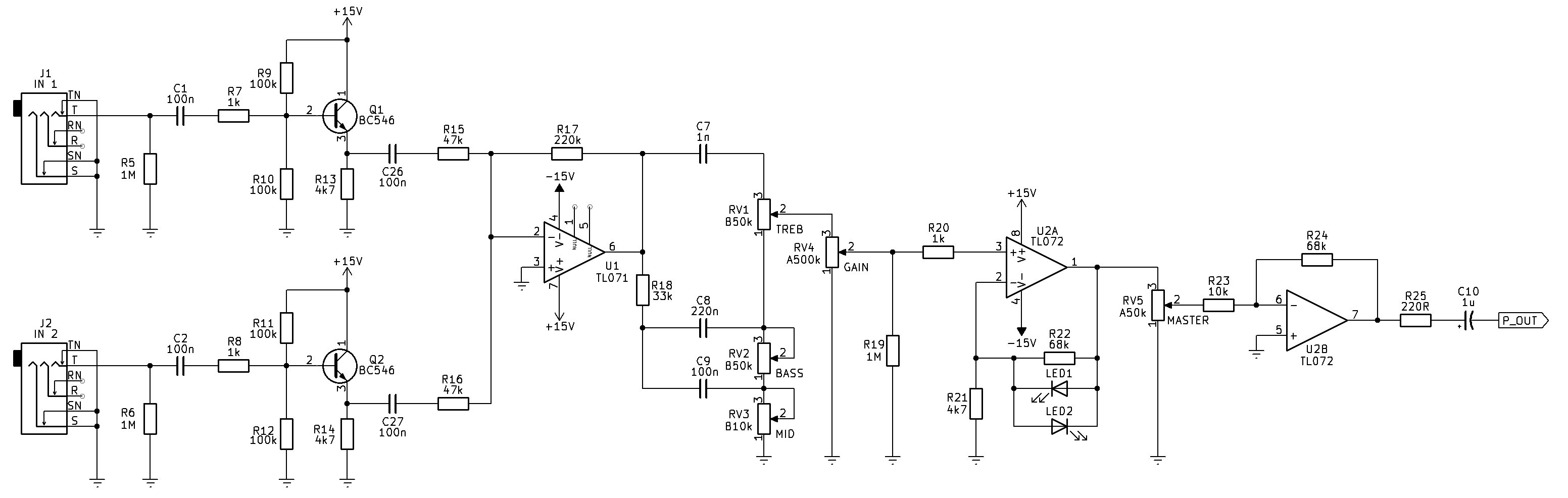
The circuit can be understood as a series of functional stages: two guitar inputs → buffer stages → mixer → tone controls → gain stage → master volume → output stage.
The two guitar inputs are identical. The first guitar enters through J1 and passes through C1, which is a 100n coupling capacitor. C1 blocks any DC voltage while allowing the guitar's AC audio signal to pass. R5, which is 1M, sets the input impedance while J1's switch (TN point of J1 - which is the tip of the plug and the contact of the switch on the connector) shorts the input to ground when nothing is plugged in preventing noise.
The signal then passes through R7, which is 1k, and reaches the base of Q1, a BC546 transistor. R9 and R10, both 100k, establish the DC bias voltage for Q1. Its collector is connected directly to +15V, while its emitter connects to R13, which is 4.7k and goes to ground.
Q1 is therefore configured as a common-collector amplifier, more commonly called an emitter follower. It has a voltage gain close to one, so it doesn't significantly increase the guitar's voltage. Its important function is to provide a high input impedance input and low output impedance. This means the guitar pickup is not heavily loaded, while the following mixer circuit can draw current from the transistor without significantly affecting the guitar.
The second guitar goes through an almost identical circuit consisting of C2, R8, Q2, R11, R12 and R14. Q2 is another emitter follower, providing the same buffering function for the second guitar.
The outputs of Q1 and Q2 are then sent through mixing resistors R15 and R16, both 47k and DC-blocking capacitors C26 and C27. These two resistors meet at the inverting input of U1, the TL071 op-amp. This stage is configured as an inverting summing amplifier. R17, which is 220k, provides the feedback from the output of U1 back to its inverting input.
Because the inverting input is held very close to 0V by the negative feedback, it acts as a virtual ground. Each guitar signal therefore flows through its own 47k resistor into the same summing node. The two signals are consequently added together.
Ignoring the small effects of the transistor stages, the gain for each input is approximately
Av = 47k/220k approx -4.68
so each guitar signal is amplified by about 4.7 times and inverted. If both guitars are producing signals simultaneously, those signals are summed at the op-amp input.
This is where the emitter-followers are particularly useful. Without Q1 and Q2, the guitar pickups would be connected much more directly to the mixer network and could load or interact with one another. The emitter-followers electrically isolate the pickups from the mixer. Each guitar therefore sees a high impedance, while the mixer sees a relatively low-impedance signal source.
After U1, the combined guitar signal enters the passive tone-control network, which is basically known as a Marshall "tone-stack" as this is what it's based on. This section contains R18, C8, C9 and the three tone controls RV1, RV2 and RV3. RV1 is labelled TREB, RV2 is BASS and RV3 is MID. Together they allow the frequency balance of the mixed guitar signal to be adjusted.
The tone-control section is passive, meaning that it doesn't provide voltage gain. In fact, it introduces some signal loss. This is compensated for by the following op-amp stage. Another thing to note, that if all three controls are rotated fully anti-clockwise, there will be no signal output - something to keep in mind when testing. Experimentation of the capacitor values in the tone network can be done if you want to tailor the sound to your own tastes. As with the values shown, the treble and middle controls have a greater affect on the signal, while the bass control is more "subtle".
The signal then reaches RV4, labelled GAIN. This potentiometer controls how much of the tone-shaped signal is sent into the non-inverting input of U2A, another section of the TL072.
U2A is configured as a non-inverting voltage amplifier. Its feedback network consists primarily of R22, which is 68k, and R21, which is 4.7k. Ignoring the effect of the LEDs for the moment, its gain is approximately
Av = 1 + 68k/4.7k
which gives approximately
Av = approx 15.5
So U2A can provide roughly 15.5 times voltage gain. This is the main high-gain stage of the preamplifier, and RV4 allows the amount of signal entering this stage to be adjusted.
LED1 and LED2 are connected around the feedback network of U2A in opposite directions. As the output signal becomes large enough, the LEDs begin to conduct on opposite halves of the waveform. This changes the feedback behaviour and causes the amplifier to limit the signal. Consequently, this section can introduce controlled clipping or distortion when the gain is turned up, which is useful in a guitar preamplifier. This method is often referred to as "soft-clipping", and doesn't sound as harsh as just allowing the op-amp to distort by over-driving it (hard-clipping).
The amount of distortion the preamplifier produces can be adjusted by rotating the GAIN control and then adjusting the MASTER control to a suitable level, obtaining a light jazz "fuzz" to full on grunge. If you'd rather a "cleaner" sound, you can just omit LED1 and LED2. The forward voltage of the LEDs are chosen for the type of "sound" you're going for. A standard is 3mm 40 - 600mcd red LEDs with a forward voltage of around 2.2V. As different colours of the same mcd range have slighlty different forward voltages, experimentation will be left up to the reader.
The output of U2A then goes to RV5, labelled MASTER. This is the master-volume control. It determines how much of the amplified signal is passed to the final op-amp stage.
U2B is configured as an inverting amplifier. The input resistor is R23, which is 10k, while R24, which is 68k, provides feedback. Its voltage gain is therefore approximately
Av = 68k/10k = -6.8
so U2B provides another 6.8 times of voltage gain while inverting the signal. This stage also inverts the signal by 180° as U1 inverts by 180° also, meaning the output will now be in-phase with the input signal(s).
Finally, the signal passes through R25, which is 220 ohm, and then C10, which is a 1u coupling capacitor. C10 prevents DC voltage from appearing at the output while allowing the audio signal to pass. The resulting signal appears at P_OUT and can be sent to the next stage, such as a power amplifier (or effects send/return loop).
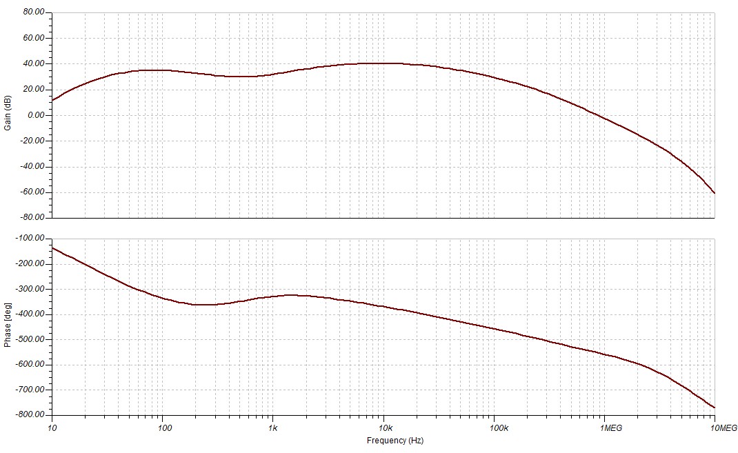
Above, is a frequency response bode plot taken directly from the simulation of the schematic. As can be seen, the curve is not completely flat due to the "tone-stack" design. However, this is for guitar - not HiFi, so is of no consequence.
Real-world Tests
At the time of writing this part of the article, I didn't have the required pots to build the tone-stack section - however, as I've bulit it many times before I know it to work fine.
First, I tested the emitter-follower and summing amplifier input stage.
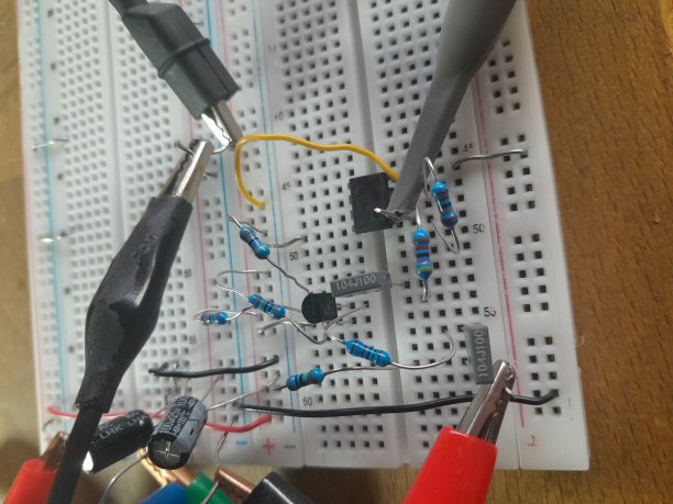
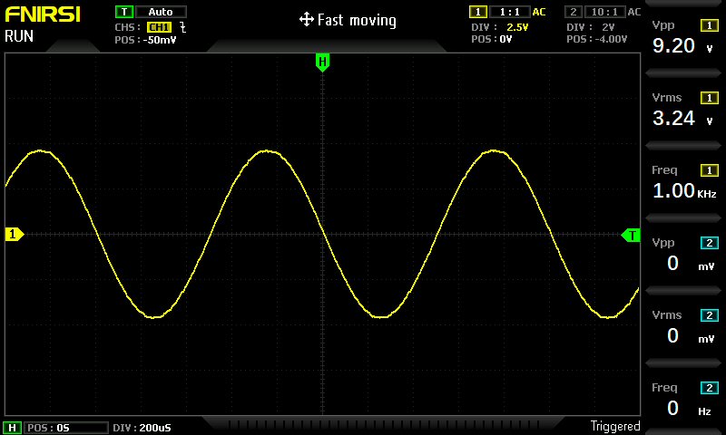
As can be seen from above, it has a clean output with no visible signs of distortion - albeit I used one part of TL072 for U1 here. I also noticed the other part of the TL072 is damaged and not producing any output - no idea how that happened.
Next, I tested the gain and soft-clipping stage. I did also build and test the output buffer amplifier, but didn't record the results here as it's unnecessary as it works as expected.
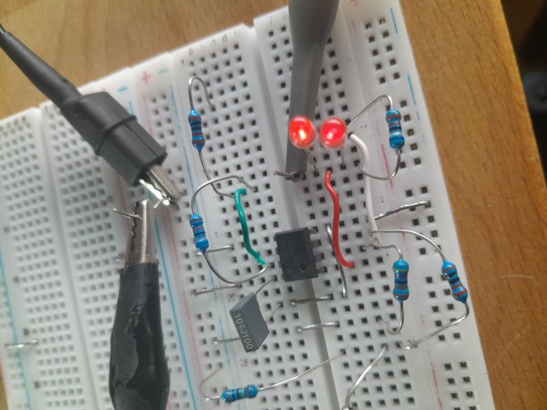
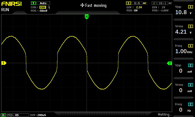
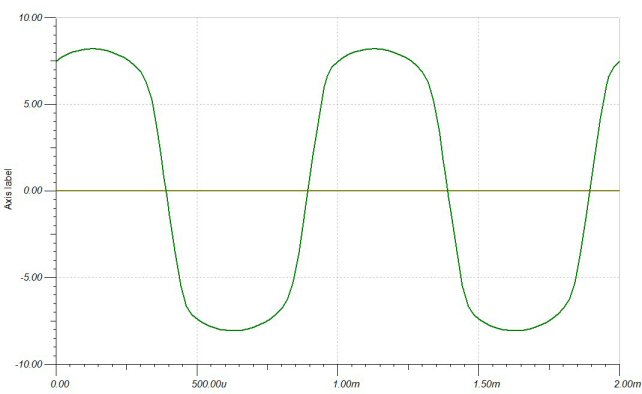
As seen from above, the output matches similar to the simulation scope output - which is nice.
Preamplifier Power Supply
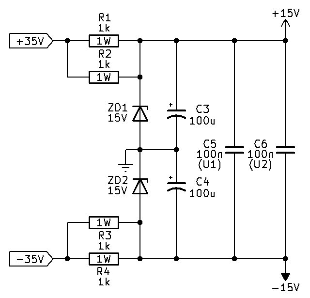
The power supply section for the preamplifier (shown above) converts the +35V and −35V supply rails into regulated +15V and −15V rails for the preamplifier. R1 and R2 share the load and drop the excess voltage from +35 V, while ZD1, a 15 V zener diode, clamps the positive rail to approximately +15V. Similarly, R3 and R4 drop the voltage from −35V and ZD2 clamps the negative rail to approximately −15V.
C3 and C4, both 100u, provide bulk filtering and smoothing between the supply rails and the centre reference, while C5 and C6, both 100 nF, provide high-frequency bypassing/decoupling between the +15V and −15V rails and the centre reference. Importantly, C5 is marked (U1) because it should be physically located close to the TL071 U1, and C6 is marked (U2) because it should be physically located close to the TL072 U2. These small capacitors help suppress high-frequency supply noise and prevent the op-amps from becoming unstable due to noise or impedance in the power-supply wiring.
FX Loop
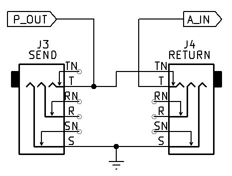
The effects send/return loop (shown below) is optional, but does provide a way for the musician to use an external effects pedal chain. As the "P_OUT" connection going to J3 doesn't disconnect the preamplifier from the power amplifier (only J4 disconnects the preamplifier output from the amplifier's input when something is plugged in), it could also be used to connect to a recording mixer.
Next, we'll move on to the power amplifier.
Power Amplifier
The power amplifier itself is based on the simple quasi-complementary design described in a previous article. So, I won't go in to an involved description of how it works. As I've already built and tested this, and confirmed it to be working well - all the technical information for it is in the previously mentioned article.
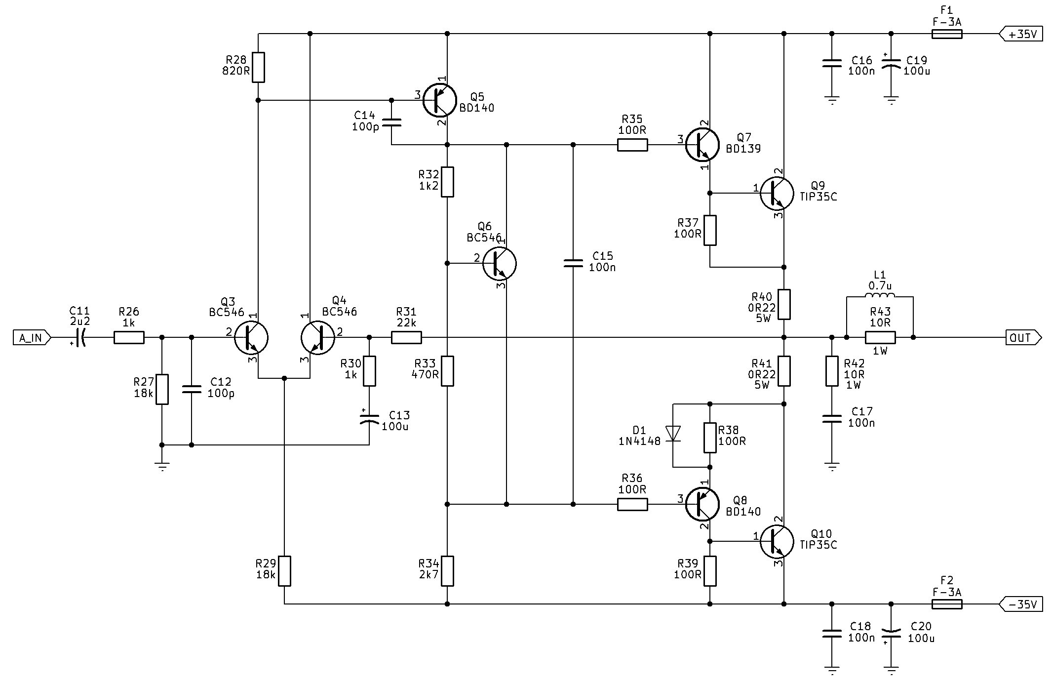
Why did I chose quasi-complementary? No reason, really. I could have gone with full-complementary, but didn't really want to. L1 consists of 14 turns of 0.4mm enamel copper wire wound around the body of R43 with each end of the wire soldered to each leg of the resistor respectively.
One thing to note: there is no output short-circuit protection, meaning if the output was shorted to ground (even if one, or both fuses blow) - the output stage could be destroyed.
I originally designed this project as a single-PCB design (even though it is a bad idea to include the high-voltage power supplies on the same board as sensitive amplification circuitry) - with the idea this was going to built in a metal chassis with it mounted inside the same cabinet as the speaker. Similar to the "combo" amplifiers you can buy from music stores.
Why buy one? It's more fun to build one! All electrolytic capacitors should be rated for 63V DC.
With the specified supply rails, the amplifier should have no trouble delievering 50W into 8 ohms and up to 70W into 4 ohms. Q9 and Q10 should be mounted on a substantial heatsink with Q6 also mounted to the same heatsink to track temperature and control bias current accordingly to prevent thermal runaway.
Main Power Supply
WARNING: THE FOLLOWING CIRCUIT INVOLVES MAINS WIRING. IF YOU ARE NOT CONFIDENT AROUND MAINS WIRING OR KNOW WHAT YOU'RE DOING, DON'T ATTEMPT TO BUILD THE POWER SUPPLY YOURSELF.
The power supply itself is pretty typical, and in actual fact, it's based on the Electronics Today International (ETI) 480 power amplifier's power supply; it was just modified to include a relay back-EMF diode and changing the position of the driver transistor to a low-side switch.
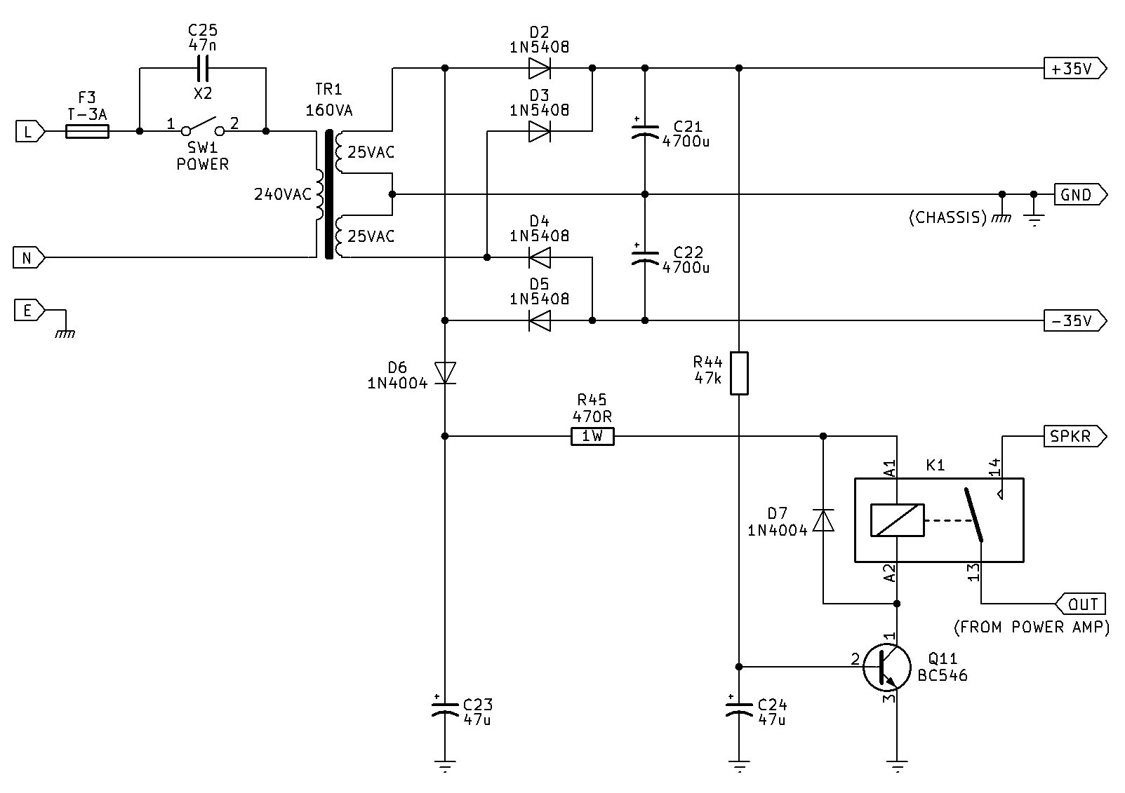
The above circuit is the main power supply and speaker muting section of the amplifier. The 240VAC mains enters through the power switch SW1 and feeds transformer TR1, which has a split secondary winding of 25-0-25VAC. C25 is connected across the power switch to reduce switching transients and electrical interference. C25 must be an X2-class and rated for 250VAC.
The four diodes D2–D5 form a full-wave bridge rectifier for the centre-tapped transformer secondary. They convert the 25-0-25VAC into positive and negative DC rails. C21 and C22, both 4700u, are the main reservoir capacitors that smooth the rectified voltage, producing approximately +35V and −35V relative to the centre-tapped GND connection. The centre of the two reservoir capacitors becomes the circuit's ground reference and is also connected to the chassis.
The +35V and −35V rails are then supplied to the amplifier's power stage. The smaller circuit involving D6, R45, C23, R44 and C24 creates a delayed or controlled voltage used for the speaker muting relay. When the amplifier is switched on, the voltage at Q11's base rises gradually as C24 charges through R44. Q11, a BC546 transistor, eventually turns on and energises the coil of relay K1. D7 is connected across the relay coil to absorb the voltage spike generated when the relay is switched off, protecting Q11.
The relay contacts connect the power amplifier's output OUT to the SPKR terminal only after the protection circuit has activated. Before the relay operates, the amplifier output is disconnected from the speaker. This provides a speaker turn-on delay, preventing the loud click or thump that can occur while the power amplifier's output is settling when the amplifier is switched on.
R45 and C23 form part of the timing/supply network for the relay circuit, while R44 and C24 control the voltage rise at Q11's base and therefore the relay's activation delay. D6 provides the relay drive current by half-wave rectifying one of the transformer's secondaries, together with C23 to provide a small amount of DC smoothing to prevent the relay "chattering". When power is removed, the relay almost instantly de-energizes, disconnecting the speaker from the output of the amplifier. This prevents any turn-off transients being presented to the speaker - which can be a loud annoying thump.
The circuit only mutes the speaker, it does not provide any DC offset protection.
All electrolytic capacitors should be rated for 63V DC. The relay shown is just generic, and can be any 12VDC SPST or SPDT relay with a coil resistance of around 270 ohms. The contact current capability should be at least 5A rated. If you find the turn-on delay too quick, you can increase the value of either or both R44/C24.